|
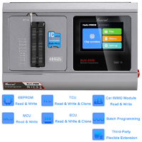
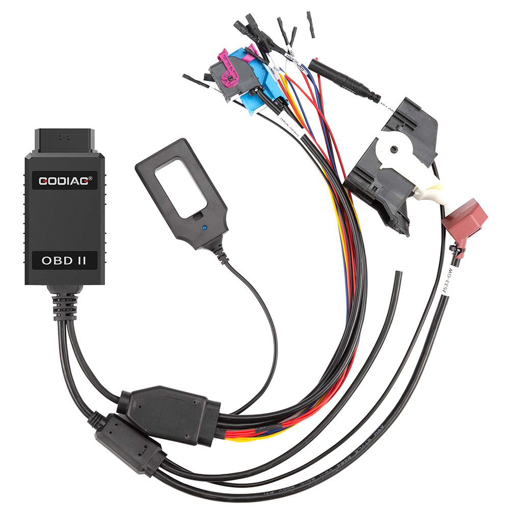
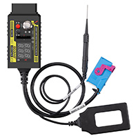
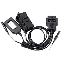
Name: GODIAG GT115 VAG MQB IMMO4 CAN-BUS UDS 4th Generation IMMO System Test Platform with Pogo Pin to Read & Write Data
Description:
GODIAG GT115 VAG MQB IMMO4 CAN-BUS UDS 4th Generation IMMO System Test Platform with Pogo Pin to Read & Write Data.
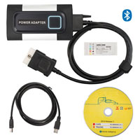
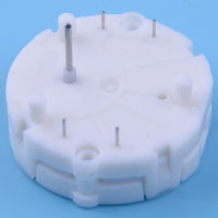
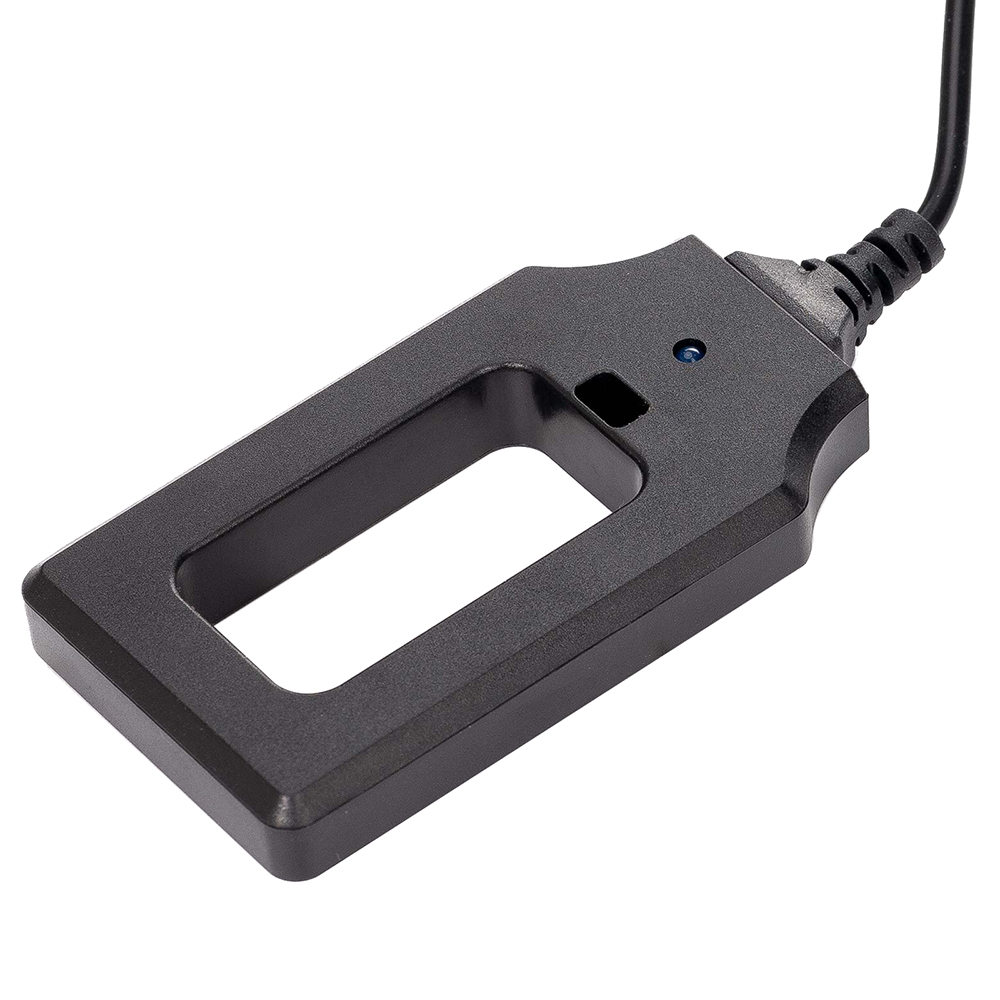
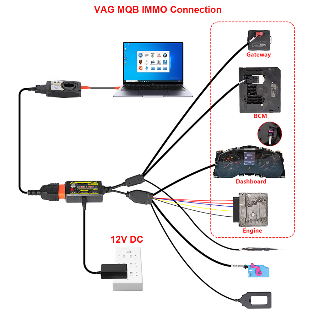
MQB models may range from super minis to large family cars, replacing the current generations of models. The MQB architecture replaces the PQ25, PQ35 and PQ46 platforms. Our product is a connecting cable designed for the MQB IMMO system, enabling engineers to conveniently perform off-vehicle operations such as IMMO programming, matching, and diagnostics on the MQB IMMO system. Moreover, it has a Pogo Pin to read and write data to the dashboard, which is more stable to hold and does not damage the cable.
Functions:
1. Synchronous detection of key and vehicle IMMO module.
2. Independent diagnosis of engine and power expansion module.
3. Communication diagnosis and programming test of engine module and power module through gateway module.
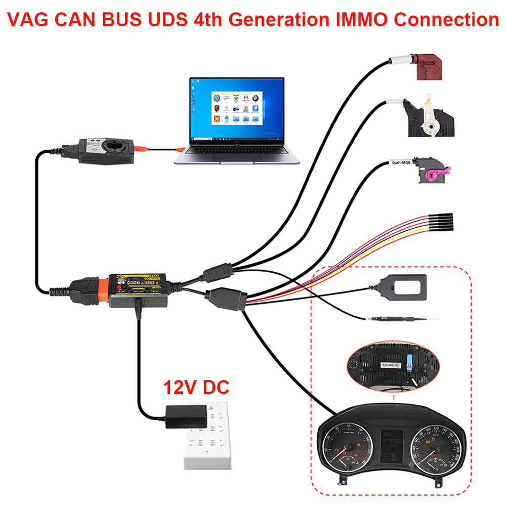
4. IMMO 4th generation POGO PIN read and write data and key synchronization detection.
5. Connect BCM module with gateway module for communication diagnosis and programming test(Note: Press the corresponding switch when required.).
6. Gateway module detection.
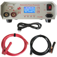
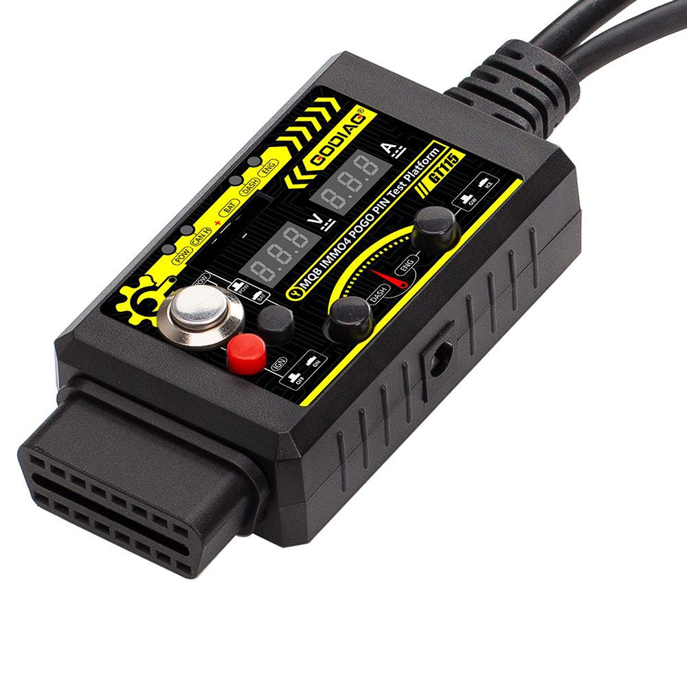
7. Current connected power supply voltage display.
8. Current connected module current display.
9. 2032 battery voltage detection..
10. With Pogo Pin to read and write data to the dashboard.
Download:
GODIAG GT115 Connection Diagram(35MB)
Features:
1. Synchronous Detection: Effortlessly detect keys and vehicle IMMO modules.
2. Independent Diagnostics: Perform standalone diagnostics for engine and power expansion modules.
3. Gateway Communication: Conduct communication diagnostics and programming tests for engine and power modules via the gateway.
4. Pogo Pin Technology: Read and write data to the dashboard with precision and stability.
5. Comprehensive Testing: Test BCM modules through the gateway for seamless communication and programming.
6. Real-Time Monitoring: Display current power supply voltage and module current for accurate diagnostics.
7. Battery Voltage Detection: Ensure optimal performance with 2032 battery voltage detection.
How to Use Pogo Pin?
1. Connect the power supply (Note: Power switch must be off.).
2. Press the IGN ignition power (IGN ignition switch must be turned on).
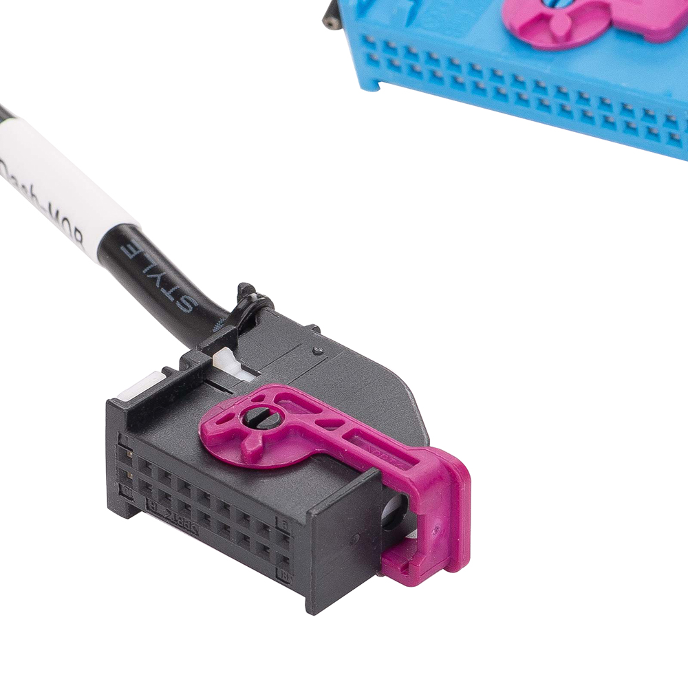
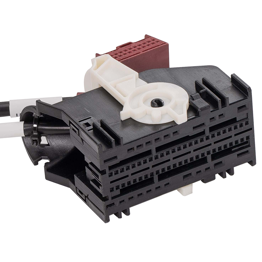
3. Connect the instrument plug.
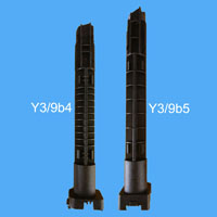
4. Find the Pogo Pin connection point of the corresponding instrument and connect it with a probe.
5. Turn on the power switch for 3-5 seconds. If the ABS light flashes, you have successfully entered Pogo Pin read/write mode.
|


.jpg)